Tank Ventilation
A 2800-word discussion in relatively non-technical language, of the problem posed by the projection of carbon monoxide into the compartments of a tank by the firing of the tank’s main weapons. Various methods of overcoming this difficulty are discussed, and a practical solution offered. Protection against chemical warfare gases is also considered.
The author (Dr Friedrich Wirth) was a German professor of physics and chemistry who apparently was engaged in tank design or production during the war. He also was an officer in the German Army. It is not possible to determine the accuracy of the translation, but the study is expressed in good, clear English and appears to be well written.
About the author: Professor Dr Friedrich Wirth was born on 26 July 1883 in Regensburg, Bavaria. He served as a second lieutenant (reserve) in the Royal Bavarian Light Cavalry Regiment Taxis nuring World War I and remained in the Army after the war until 1923.
From 1924 to 1933 he lectured as a professor of chemistry and physics at the Technical College, Berlin and at the same time was at the heart of the Gas Analysing Institute there, but in the latter year was suspended by the National Socialist Government under suspicion of anti-Nazi activities.
In 1935 Wirth joined the Wehrmacht as an Army official and in 1939 was promoted to the rank of Ministerialrat. He remained in the employ of the Wehrmacht as a section chief in the Army Ordinance Office until the war ended.
Professor Wirth wrote and published quite a number of works on chemistry and on physics, incluing books on gas an air defense.
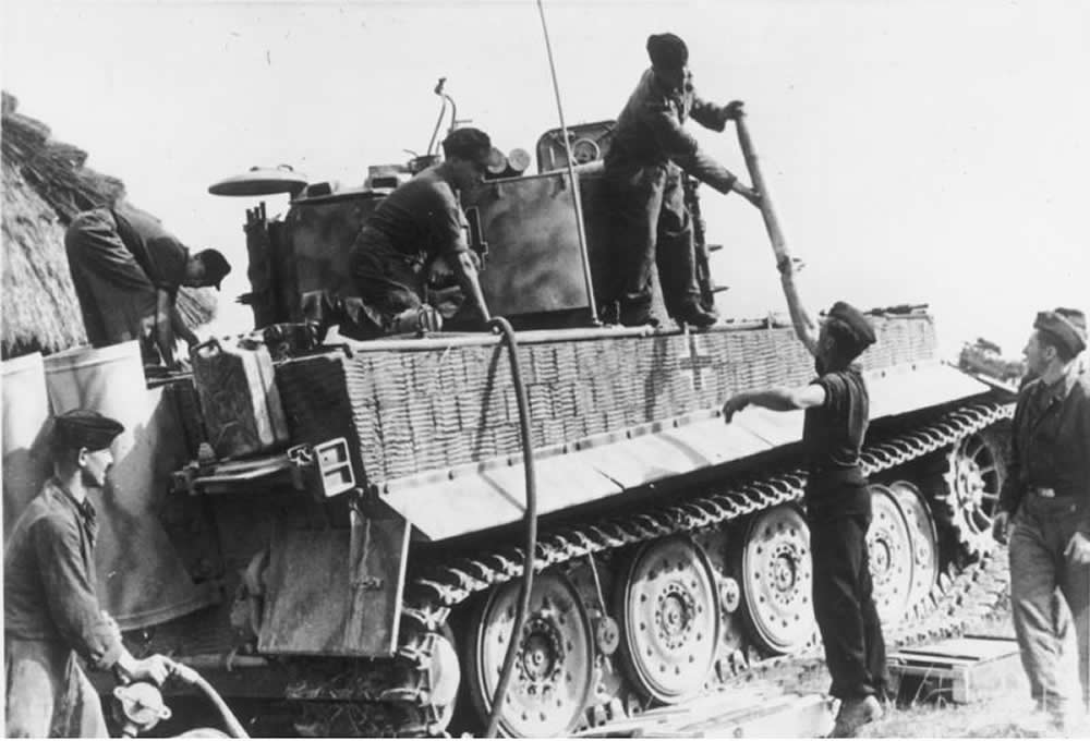
A German Tiger I tank of 2./Heavy-Panzer-Battalion 509 during refueling and replenishing of ammunition, Lublin area, Poland, July 1944. (Bundesarchiv)
Protection Against Carbon Monoxide and Chemical Agents in Armored Vehicles
1.
When an artillery piece or a machine gun is fired from an armored vehicle, which is a more or less tightly closed space, a considerable concentration of carbon monoxide emanating from the burning power is produced inside the vehicle. These powder gases, consisting of about 50 percent carbon monoxide, escape from discharged artillery or machinegun cartridge cases. Also, particularly in the case of automatic weapons, they escape from the breech mechanisms and iron the tube of an artillery piece during extraction of the case.
As always, the degree of concentration of the gas depends upon the size of the space, the amount of ventilation, the caliber of the gun and its rate and duration of fire. During rapid fire, considerable quantities of carbon monoxide appear after only a few minutes, particularly if ventilation is inadequate. Thus, it was often observed that the crew of the French Somua tank came out of the smouldering vehicle staggering as if stupefied, after firing at a normal rate, although no burning has taken place inside the tank.
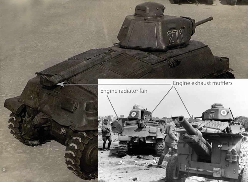
The collage shows the exact locations of the engine radiator fans and exhaust mufflers, as well as the turret hatches of the French Somua S35 tanks. The larger photo portrays a German Panzerkampfwagen 35-S 739(f) (ex-Somua S35) captured by the Soviets in the course of the war. In the smaller photo you can see two Somua S35s of the French 18e regiment de dragons (18th Dragoon Regiment) abandoned at Dunkirk in May 1940. (TsAMO and Bundesarchiv)
2.
One reason for this very disagreeable concentration of carbon monoxide was the fact that in none of the known types of tanks employed by the armorer forces of the nations participating in World War II was the cartridge case removed from the cockpit immediately after every shot. Obviously this was considered superfluous, an no type of tank was provided with a device for removing cartridge cases from the tank. In contrast to this, in fortified defense systems an effort was always made to remove cartridge cases from an emplacement immediately. Yet a tank, of course, is nothing other than a small mobile fortress!
The problem of carbon monoxide control is generally closely connected with that of tank ventilation, which is accomplished in two ways. First, a ventilator for the escape of gases is built into the roof of the so-called commander’s turret. Its capacity is roughly from two to three cubic meters a minute. Furthermore, the engine does not take the air necessary for combustion directly from the outer air, but sucks all or part of it from inside the fighting compartment, which, when the engine is running, is thus rendered sufficiently clean. On account of the partial vacuum thus produced, fresh air streams into the tank through crevices and apertures made expressly for the purpose. This is called vacuum ventilation.
This kind of ventilation has the following characteristics:
a. The instreaming air current cannot be pre-heated. This produces a very disagreeable problem, as it is not easy during a cold winter to make use of the radiator heater for heating the air in the compartment.
b. The incoming air cannot be cleaner, there being no way to control its current, although such control is a prerequisite for air cleaning, i.e. for protection against gas.
c. As a result of the partial vacuum, powder gases are sucked from the gun tube into the cockpit.
3.
In conjunction with vacuum ventilation, so-called “tube rinsing” was often used. A device was installed by means of which, immediately after each shot, the tube was “rinsed ” by a short gust of air; but this made necessary either a compressor driven by the engine or a high pressure air container, and of course an appropriate device at the breech mechanism. Such a system prevents penetration of power gases into the compartment while the breech is open, but it demands fairly complicate devices and, without removal of the cartridge cases, is not a fully satisfactory means for solving the problem of carbon monoxide.
4.
Much better results are obtained if, instead of vacuum ventilation, a system of “overpressure ventilation” is used, i.e. if the necessary air is forced into the fighting compartment by pressure. By this method it is possible to control the flow any supply of air. The air is introduced through an opening by suction. It can then either be forced into the fighting compartment directly or it can also be cleaned by a “collective protector” (air filter). A prerequisite is that the compartment which is to be ventilated be “gas-proof.” This means that the compartment receives air exclusively through an air duct manifold attached to the pressure site of the ventilator. It is important that at no time more air be exhausted than is being forced into the room through the duct, so that a constant overpressure is maintained. This means that the fighting compartment of the tank, in which the gun and the observer are located, must be sealed off from the engine room and the driver’s compartment, as otherwise a partial vacuum would develop in the fighting compartment. Furthermore, the fighting compartment, which alone can be fitted with an air filter, must be sealed off from other spaces which likewise need air, as for example the brakes for ventilation. This is by no means an easy task, but it can be carried out when new designs are made. Illustration 1 shows a control chart of a modern air supply system of a tank with ventilation and collective gas protection. The air intake on the outside of the tank is fitted in such a way as to insure that rain water and liquids, such as gasoline thrown on the tank, cannot penetrate into the air filter. If need be, a sediment bulb with water outlet can be inserted between (A) and the dust filter (1). Before (A) an additional screen or strainer must be installer, to exclude larger particles.
The dust filter (1) is necessary because tanks very often, as for example in march column, have to drive through enormous clouds of dust. A centrifugal Dust filter from which the separated dust can be easily removed has proved to be very efficient. Exchangeable cloth filters (bags) and cellulose filters in small containers have also been used. The filters must always be easily exchangeable and highly efficient. They were installed in such a way that the accumulated dust did not clog the air ducts, but was shaken out by the jolting which occurred when the tank was in motion.
The air filter (3) was designed with a capacity of from 2 to 2.4 cubic meters a minute. As a rule two such filters were operated in parallel. Thus, when both protectors were switched on, the quantity of air filtered was roughly five cubic meters a minute.
If the air current, during simple ventilation, passes from A to 7 via 1, 2, 5 and 6, roughly seven or seven and half cubic meters of air a minute will be filtered.
This quantity of air is sufficient to remove the carbon monoxide. In cold weather it will naturally be throttled so as to prevent too much cold air’s being forced into the fighting compartment. If there is no danger of gas, and none is expected under normal conditions, the route A, 1, 2, 5, 6 will always be used so as to save the filtering equipment.
The ventilation (6) is a centrifugal ventilator designed to work against a total resistance in the tubing, and the gas filter equivalent to the pressure exerted by a water column of about 120 mm. It runs partly on ball bearings and partly on plain bearings. It would be very simple to run it from the storage battery of the vehicle, in which case it could be operated even when the engine is not running. As a rule this cannot be done because of the insufficient capacity of the battery. Therefore, it may be advisable to power it through an auxiliary drive from the engine, an arrangement which has the disadvantage that the ventilator can be operated only when the engine is running.
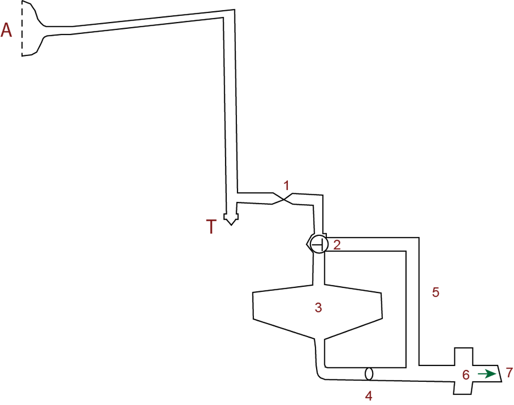
Illustration 1 (Kamen Nevenkin)
5.
From a purely technical point of view the design and installing of gas protection equipment in tanks presented no difficulties. Of course, a certain delay in production of the tanks occurred on account of such installation, and the amount of ammunition carried had to be reduced by from about 13 to 15 percent, since only by such reduction could the necessary space for the air filter equipment be made available. Owing to lack of space the equipment could not be installed in any other way, and for reasons of security it has to be installed inside the tank. The gas filters were place in square boxes which could be speedily replaced. Servicing the equipment was the simplest matter imaginable, and the benefits obtained from the equipment in case of chemical attack would have been enormous.
Nevertheless, opposition to anti-gas equipment on the part of tank crews was great. It was based less on space considerations, i.e. the reduction of the ammunition stock by from 13 to 15 percent occasioned by the installation of the equipment, than on opposition to the demand of the chemical defense officers that the fighting compartment be transformed into a gas proof space. This meant that the partition between the fighting compartment and the driver’s compartment had to be made gas-tight and that any connection between the fighting compartment an the spaces which had to operate under partial vacuum, as for example the brakes, had to be avoided. As a consequence, new designs had to be made and the production of tanks was again delayed. Ultimately it was decided that after a certain deadline all the fixtures and other appliances which were necessary for the installation of gas protection equipment were to be built into the tanks which were in production at the time (Tiger and Panther). Then, whenever ordered, the equipment could be installed at the front by the maintenance platoons assigned to the panzer divisions. The filters themselves were to be manufactured and stored with the rear services, ready for shipment. The space necessary for installation of the gas filters could be occupied by other materiel only to such an extent that it would not interfere with the installation of the equipment when ordered.
From the point of view of gas protection this solution was not satisfactory, since if chemical warfare should suddenly begin it would take a considerable time to bring up and install the gas protection equipment. Still, an arrangement was arrived at by which every new tank was delivered with its fighting compartment “gasproofed,” i.e., cut off from the driver’s compartment, which either could not be made gas proof or could be made so only with great difficulty because of the partial vacuum in it.
It is my conviction that in future “overpressure ventilation” will be adopted in tanks, as only thus will it be possible to control conditioning of the air in them.
In overpressure ventilation the air can be cleaner by rust filters, free from chemical warfare agents and pre-heater in winter. The overpressure in the fighting compartment prevents outer air, which in certain cases may contain chemical warfare agents, from entering through leaky places and lessens the danger of carbon monoxide during firing from the tank.
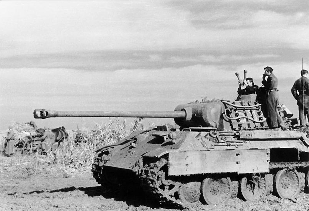
A Panther tank of 23. Panzer-Division in eastern Hungary, Autumn 1944. The commander uses a scissor periscope. (Bundesarchiv)
6.
Measurement of carbon monoxide content during our fire from the tank (Tiger) showed the following results:
a. Vacuum ventilation. Running engine. Roof (turret hatch) ventilation switched on. No tube “rinsing” Turret hatch closed. Empty cartridge cases retained in the fighting compartment. Result: After every shot there was smoke in the compartment. The concentration of carbon monoxide was from about 0.05 to 0.1 percent. Within one or two minutes after cessation of fire, the concentration of carbon monoxide faded practically to zero, Improvement was obtained through the expedient of covering every cartridge case with a wooden lid immediately after extraction from the tube. Simultaneous firing of the gun (five rounds) and the machinegun (250 rounds) caused a carbon monoxide concentration of from 0.1 to 0.2 percent. Opening the turret hatch mare very little change in the initial concentration, but increased the speed of fading or the carbon monoxide content in the fighting compartment. “Rinsing” of the tube prevented powder smoke from entering the fighting compartment.
b. Overpressure ventilation. Running engine. The lids were closet. The ventilation was switched on. No ceiling ventilation. No tube rinsing. The empty cartridge cases were retained in the fighting compartment but were covered with a wooden lid immediately after leaving the tube. Result: After every shot the power smoke was blown out of the tube into the outer air, an effect which could easily be observed. After the firing of five rounds from the gun and 250 rounds from the machinegun, the air in the fighting compartment was practically clear. From 0.02 to 0.04 percent carbon monoxide was measured immediately after firing. About ten or fifteen seconds after the last shot the carbon monoxide concentration in the fighting compartment faded practically to zero.
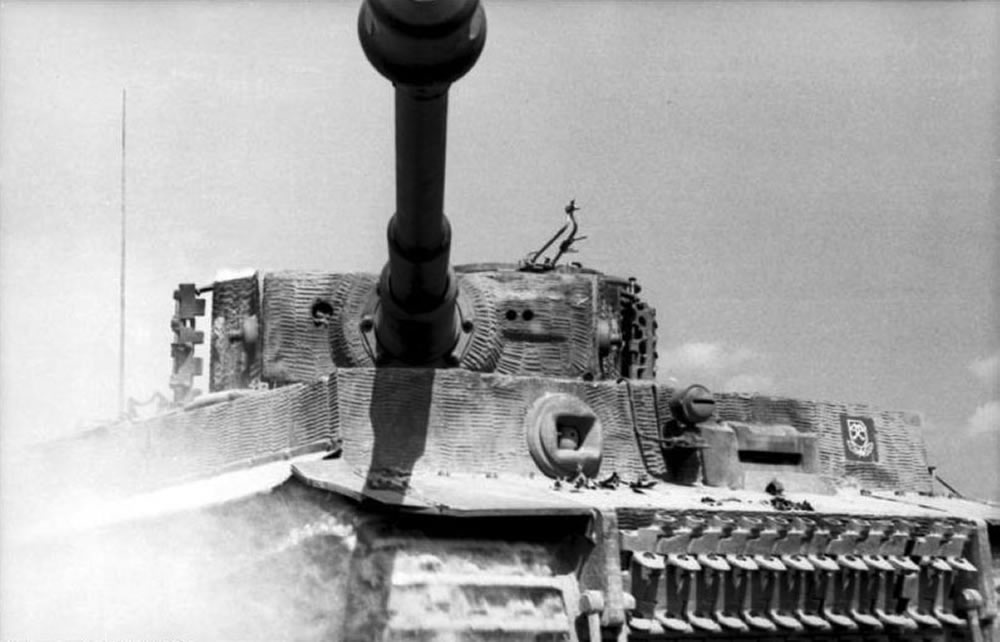
A Tiger I tank of schwere SS-Panzer-Abteilung 101 (Heavy SS-Panzer Battalion 101) somewhere in France, 1944. The Leibstandarte insignia is clearly visible on the frontal hull armor. (Bundesarchiv)
7.
Very interesting was the gas protection equipment developed for ambulances and similar vehicles. At first we tried to install collective protection equipment, consisting of a dust filter, tubing, a collective gas filter and a ventilator with hand and motor drive. The dust filter was a container with an interchangeable cloth filter. It was installed in such a way that the dust could not settle and choke the filter while the vehicle was in motion. At first the “collective gas filter” (air filter) consistent of a combined dust and gas filter (charcoal filter) with a capacity of 1.2 cubic meters per minute. When the procurement of this item became more any more difficult, the problem was solved in a satisfactory way by means of the Grabenfloete (“trench flute”).
By means of this “trench flute” high-quality collective gas protection could be effected without the need of special collective protector equipment. Collective protectors having capacities of 0.6, 1.2 and 2.4 cubic meters of air per minute were installed in fixed fortifications only. For the “trench flute” only the usual military type gas mask canisters were necessary. The number of canisters depended on the amount of air needed at a given time: for 500 liters of air per minute, from eight to ten canisters were necessary. They could be installed in the following two ways:
a. Installation of the “trench flute’ outside the gas protected space:
In order to protect it from rain, etc., the appliance (1, Illustration 4) into which the canisters were screwed was suspended at the entrance to the shelter. It was made of sheet-metal and was provided with standard thread sockets for the canisters. Screw sockets which could not be fitted with canisters had to be sealed with protecting caps. The pipeline (2) led to the shelter (S). The ventilator (3) was installed in the shelter (S).
b. Installation of the trench flute” inside the gas shelter:
In this arrangement the “trench flute” was installed in the shelter (S), where it had better protection against weather conditions. Illustration 1 shows the “trench flute” with canister sockets on one side, Illustration 2 with sockets on either side. By means of the pipe-line (2) it was connected with the intake (1). The canisters were placed in a box covered either with one lid (D1) or with two lids (D2 and D3). By this means a proper current of air was assured, and the canisters could be exchanger. The pipe-line (3) led to the ventilator (4).
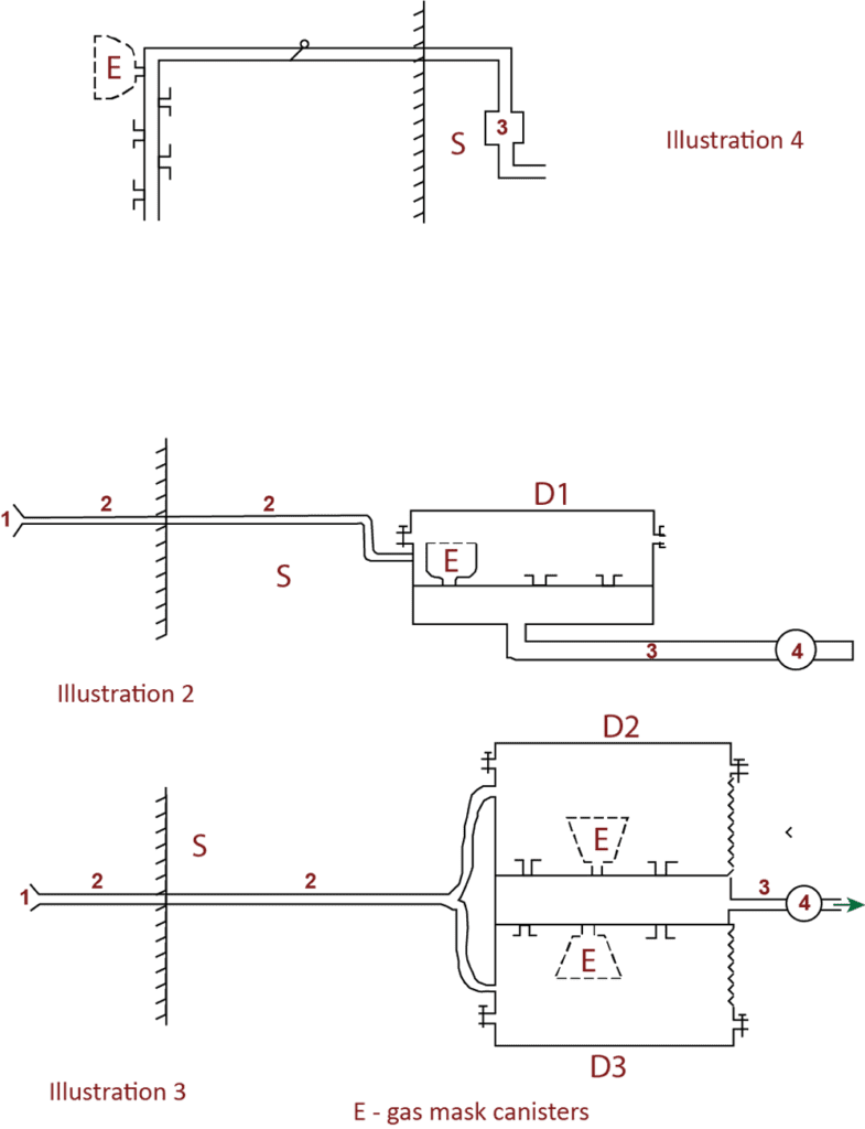
Illustrations 2, 3 and 4 (Kamen Nevenkin)
8.
During further development of gas protection equipment for ambulances another solution was found. The supply to any space, including a motor vehicle, of pure air, even when there is danger from gas, depends not only on the quantity and purity of the air conveyed into that space, but also on the degree to which the space itself is gas-tight. Only if the space is absolutely gas-tight can there be a guarantee that only pure air will enter it. However, after some time air leaks will inevitably develop at windows, frames and doors, through which unfiltered air will be pressed into the rooms, even if it is fitted with a “collective protector.” Besides, there always remains the danger of breakage of the windows and the possibility of penetration from enemy fire.
Therefore, something intermediate between collective and individual protection was devised. A trench-flute type collective protector was installed, and on the pressure sire of the ventilator a manifold system was inserted by means of which purified air was pressed under the face pieces of the gas masks for heart casualties. The canisters of these gas masks could also be used in the collective protectors (Illustration 5).
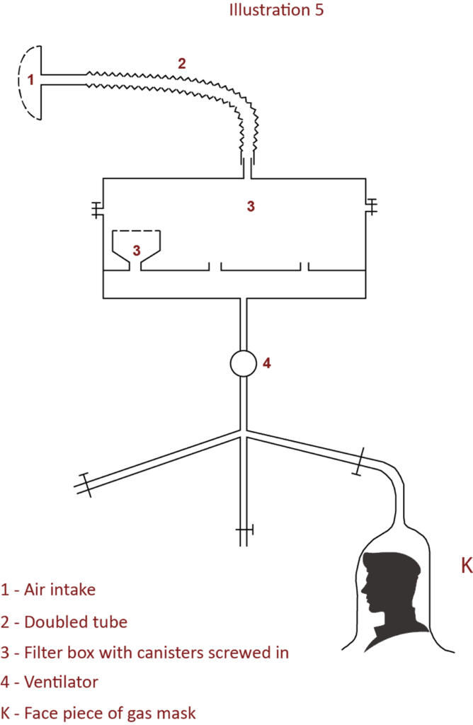
Illustration 5 (Kamen Nevenkin)
Notes: The manuscript was presumably completed in January 1951. Translator: A. Rosenwald; Editor: Dr O. J. Frederiksen; Reviewer: Capt. B. K. Hufford
Source: NARA, Foreign Military Studies, P-002 “Tank ventilation”.